


Product Description
The Ethernet Switch is a 5-port 10/100 Ethernet switch designed to integrate perfectly with the Fathom-X Tether Interface Board, providing three additional Ethernet ports for accessories on the BlueROV2. This switch was designed in collaboration with BotBlox and leverages their extensive expertise on Ethernet switches for robotics applications!
Why do I need an Ethernet switch?
Ethernet networks form a high-speed connection between computers and they are a backbone of the internet! We also use an Ethernet network on the BlueROV2 that connects the surface computer to the ROV’s onboard computer, providing a high-speed connection that carries telemetry data and video. There’s a lot of extra bandwidth available on that network that can be leveraged for other devices, like sonars, IP cameras, and sensors.
Ethernet allows multiple devices to be connected to the same network, however, you can’t simply connect all the cables together, you need an Ethernet switch to route data between connections. This Ethernet switch does exactly that! With 5 ports, two are used to connect to the existing Fathom-X and Raspberry Pi computers in the ROV, leaving three additional ports for expansion!
Just imagine what you can do with three more ports! You could add a multibeam imaging sonar, add an additional computer for dedicated computer vision processing, or connect a high-end IP camera for new video options! The possibilities are endless!

How does it integrate?
The Ethernet Switch is designed to be a perfect complement for the Fathom-X board. It has the same dimensions and mounting holes so that it can stack on top. Two RJ45 port connections are available to quickly connect the Fathom-X and Raspberry Pi through the switch, while the remaining connections are broken out to JST-GH connectors that follow the Blue Robotics Connector Standard. The board can be powered from a wide voltage input up to 60V and has low power consumption. Indicator lights show activity on each port.
The switch comes with an RJ45 to JST-GH adapter board to make it easy to connect your Ethernet device during testing, but we recommend solder splicing one of the included JST-GH cables to your device for long term integration on an ROV since a standard RJ45 connector does not fit through a cable penetrator hole.
The Ethernet Switch is cool, but what you integrate with it is the really cool part! Please feel free to share your integration on the Blue Robotics discussion forum where it might help others to find new ways to use their ROV.
Contents
- 1 x Ethernet Switch Board
- 1 x RJ45 to JST-GH Adapter Board
- 3 x 200mm JST-GH to JST-GH twisted pair cable
- 1 x 150mm Ethernet cable
- 1 x Power cable with spade connectors
- 2 x 18mm mounting standoffs
- 4 x M3x5 mounting screws
Specifications
| Parameter | Value |
|---|---|
| Electrical | |
| Supply Voltage (wide range input) | 7-60 volts (reverse polarity protected) |
| Supply Voltage (5v input) | 5 volts |
| Idle Power Consumption | 300 mW |
| Max Power Consumption | 700 mW |
| Power over Ethernet (PoE) | Not supported |
| Performance | |
| Ethernet Speed | 100 Mbps |
| Ports | 5-ports |
| Physical | |
| Operating Temperature | -20 to +85°C |
| Storage Temperature | -40 to +85°C |
| Dimensions | 64 x 46 mm |
| Screw Hole Spacing | 57 x 40 mm |
| Screw Hole Diameter | 3.3 mm |
| Cable Length (included accessory cable) | 200 mm |
| Connectors | |
| JST GH Connector Type | BM04B-GHS-TBT(LF)(SN)(N) (on the PCB) |
| JST GH Plug Housing and Crimp Pins (not included) | GHR-04V-S (housing) MINI-SSHL-002T-P0.2 (pin) |
| Data Connector Pinout | 1 – TX+ 2 – RX+ 3 – RX- 4 – TX- |
| Power Connector Type | BM02B-GHS-TBT(LF)(SN)(N) |
| Power Connector Pinout | 1 – V+ 2 – Ground |
Testing Results
3D Models
ETHSWITCH-R1 (.zip)
Revision History
7 September 2021 | ETHSWITCH-R1-RP – Initial release
Quick Start
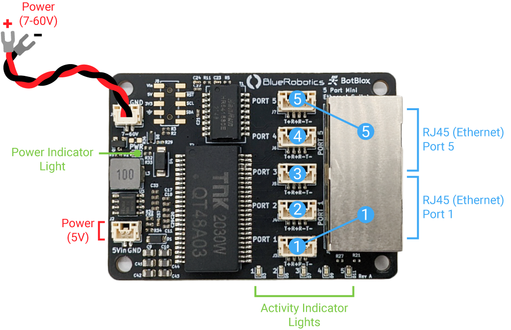
- Connect the power cable to the 7-60V JST-GH power connector in the top left of the board. Apply 7-60V DC to power the board.
- Alternatively, the switch can be powered with regulated 5V DC using the 5V JST-GH connector at the bottom left of the board.
- Do not supply higher than 5V DC when using the 5V power input.
- Do not use both power inputs at the same time.
- Connect your devices to ports 1-5 using either the included JST-GH to JST-GH twisted pair cables, the included RJ45 to JST-GH Adapter Board, or directly to the RJ45 jacks.
- The Ethernet switch is an unmanaged switch so no configuration is required. Just connect a device and the switch will automatically begin forwarding packets.
- The pinouts for the JST-GH connectors follow the Blue Robotics Connector Standard for Ethernet connections.
- Ports 1 and 5 are each broken out to both a JST-GH connector and an RJ45 jack that accepts regular Ethernet cables.
- Only one device should be connected to either the JST-GH connector or the RJ45 jack on ports 1 and 5. Connecting multiple devices to the same port will lead to communication problems.
- Indicator lights at the bottom of the Ethernet switch will show the activity on each port.


Reviews
There are no reviews yet.